
In our CFD Evacuation Lift Olympics, we will be awarding medals for the best way to ventilate an evacuation lift lobby. Innovation Fire Engineering have completed four internal CFD case studies to investigate various ventilation strategies for both the common corridor and the evacuation lift lobby within a residential building. A total of four possible ventilation options have been assessed – as shown in the table below.
The bronze medal for ventilating an evacuation lift lobby goes to Solution 1, see details below.
Table 1 – Ventilation options modelled in Solutions 1–4
| Solution | Common Corridor | Evacuation Lift Lobby |
| 1 (‘Code-compliant’) | 1.5m² Natural Shaft | 1.5m² natural smoke shaft |
| 2 (‘Fire Engineered’) | Mechanical Shaft | Cross-vented via stair AOV (double ‘floppy door’) |
| 3 (‘Fire Engineered’) | Mechanical Shaft | 1.5m² natural smoke shaft |
| 4 (‘Fire Engineered’) | Mechanical Shaft | 1.5m² AOV |
Background
In March 2024, amendments were made to Approved Document B Volume 1 (ADB V1) seeking to provide new guidance on residential buildings over 18m and evacuation lift lobbies. As well as requiring a second stair in residential buildings taller than 18m, ADB V1 amendments stated that an evacuation lift lobby should provide a refuge area for those waiting for the evacuation lift, to not be directly accessible from any flat and that any smoke control system designed to protect the staircase should extend the same level of protection to the evacuation lift and evacuation lift lobby.
CFD Modelling Details – Solution 1
The CFD geometry is based on a generic corridor and lift lobby arrangement, whereby the maximum single direction travel distance within the common corridor is 7.5m (ADB Vol 1). Building height is assumed to be over 30m and the single stair modelled to its full height. The corridor is assumed to be a dead-end portion.
In Model 1, both the common corridor and the evacuation lift lobby are ventilated via separate 1.5m² natural smoke shafts. This is a slight enhancement of a code-compliant design. Figure 1 shows the generic design for Solution 1.
The fire size, CFD parameters, and timeline are consistent with industry practice and guidance.
Figure 1 – Solution 1 CFD domain (plan view)

CFD Results – Solution 1
Please see the smoke and visibility videos below.
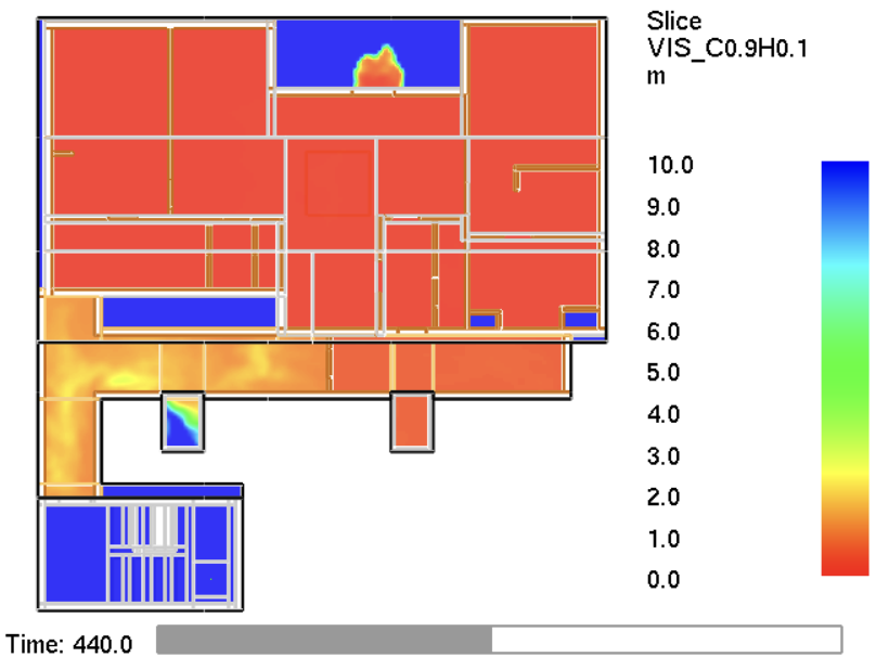
For Solution 1, smoke breaches the evacuation lift lobby during escape and does not fully clear. This is not acceptable and is due to lack of resupply air when doors close.
Figure 2 – Visibility at t=440s
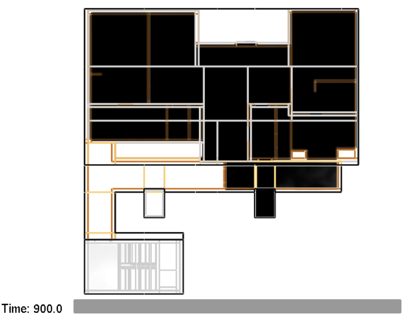
During firefighting, doors remain open creating a push-pull effect between shafts, clearing smoke effectively and making conditions acceptable.
Figure 3 – Smoke at t=900s
Discussion
Solution 1 shows unacceptable escape conditions but acceptable firefighting conditions. There is clear scope to improve the ventilation strategy.
We invite feedback on Solution 1 and the wider approach to lift lobby ventilation.
Next week, Innovation Fire Engineering will award the Silver Medal in our CFD Evacuation Lift Olympics.